Interactive 3D Building Designer for Direct Customer Specification
Let customers place doors and windows in a 3D model so the office does not re-enter or reinterpret their intent.
- Creator
 TheAMEConnect
- Improvement date
- June 16, 2024
- Company
 Southwest Steel Buildings
- Wastes
When customers describe door and window locations verbally or on paper, office staff must translate that intent into engineering specs. Each hand-off adds a chance to mishear, misplace, or misinterpret, creating defects that surface late in production.
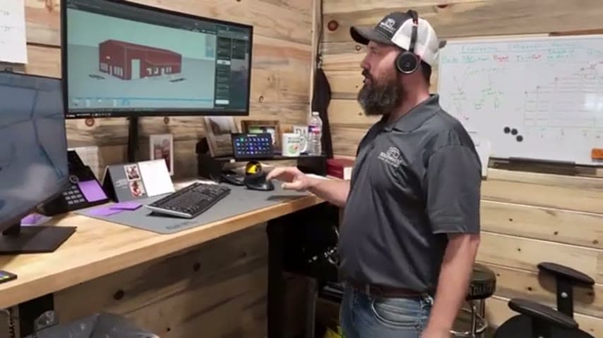
The engineering and estimation team gave customers an interactive 3D building designer where they place door and window locations directly on the model. The customer's own placement becomes the spec, so there is no office translation step to introduce errors.
Capture requirements at the source so intent transfers once, without reinterpretation.
What is a Interactive 3D Building Designer for Direct Customer Specification?
An interactive 3D building designer is a tool that lets the customer configure the actual product model, in this case a metal building, and drop doors and windows exactly where they want them. The design output flows straight into engineering and estimation.
The team frames this as single second exchange of information: the customer's intent is captured in one clear digital act rather than passed through phone calls, sketches, and manual data entry. What the customer sees and places is what engineering receives.
Because the customer authors the specification themselves, the office no longer acts as a translator between what was said and what gets built. This removes both the overprocessing of re-keying details and the defects that come from misreading them.
Why it works
It makes the customer's exact intent visible and reusable downstream instead of buried in a conversation someone has to interpret.
- The specification is authored once by the person who owns the requirement, removing a reinterpretation step.
- A shared 3D model becomes the single source of truth that engineering, estimation, and production all reuse.
- Mistakes are proofed out at the source: what the customer placed is what everyone downstream sees.
- Adds value by turning a vague description into a precise, transferable design artifact.
How to create this idea
- 1Map the translation hand-offs
Identify every point where customer intent is described, re-entered, or interpreted by staff before it reaches engineering.
- 2Build a customer-facing configurator
Create an interactive 3D model of your product that lets customers place variable features, such as doors and windows, directly.
- 3Make the model the spec
Feed the customer's placements straight into engineering and estimation so no one re-keys or reinterprets them.
- 4Confirm at a glance
Use the shared 3D view so the customer and the office are looking at the identical placement before work begins.
- 5Track defect reduction
Measure door and window placement errors before and after to verify the office translation step is eliminated.
Best used when
- configurable products
- customer-specified layouts
- frequent spec errors
- quote-to-engineering hand-off
Less useful when
- fully standard products
- no customer variation
- one-off custom engineering
Tags
- Problem
- translation errorsreworkmiscommunication
- Lean methods
- error proofingsingle exchangesource capture
- Application
- engineeringestimationmetal buildings
Captured from TheAMEConnect at Southwest Steel Buildings in the video "AME 2 Second Lean Tour: Southwest Steel Buildings", at 00:11:22. On Lean Toolbox. Watch the original video on YouTube ↗