First-Part Inspection Jig With Feeler Gauges for Bend Angles and Spacing
A dedicated jig and feeler gauges let an operator verify gaps, spacing, and bend angles on the first part before a run begins.
- Creator
 WillytheMinimalist
- Company
- Stamping Plant
- Wastes
Bent and formed parts have gaps, spacing, and bend angles that are hard to measure repeatably with hand tools alone. Without a fast, standard check, out-of-tolerance parts slip through and a whole run can be built wrong.
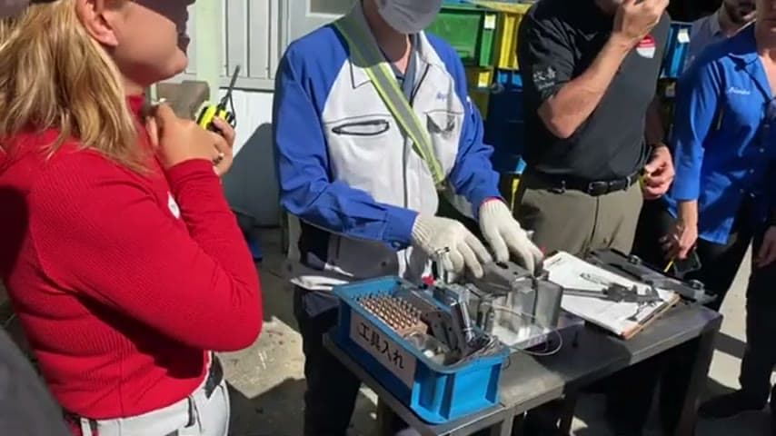
The operator first reads the specs and records actual measurements with a dial caliper to confirm dimensions are in tolerance. He then clamps the part into an inspection jig and uses feeler gauges to check that the correct feeler fits into every gap, confirming bend angles and spacing across the part.
Build inspection into a fixture so first-part quality is verified the same way every time.
What is a First-Part Inspection Jig With Feeler Gauges for Bend Angles and Spacing?
An inspection jig is a fixture that holds a part in a known position so that its critical features line up with reference surfaces or gauge points. Once clamped, the part can be checked against the jig instead of measured feature by feature by hand.
Feeler gauges are thin blades of precise thickness. When paired with the jig, a specific feeler either fits into a gap or it does not, giving a fast go/no-go read on gaps, spacing, and effective bend angle without a protractor or repeated caliper readings.
Here the check runs in two stages. A dial caliper confirms the numeric dimensions against the spec sheet, with actual values written down. Then the jig and feelers confirm the geometry that is awkward to measure directly, the bend angles and the spacing between features.
Why it works
The jig turns one person's knowledge of what a good part looks like into a reusable, mistake-proofing check anyone can run.
- The correct spec is captured once in the jig, so proven tolerances are reused on every first part.
- Feeler gauges give a clear go/no-go answer, removing operator judgment and reading errors.
- Recording actual measurements against spec makes tolerance decisions visible and traceable.
- Catching a bad first part stops the same defect from being repeated across the whole run.
Evidence: The operator writes down actual measurements next to spec values to confirm the part is in tolerance before clamping it in the jig.
How to create this idea
- 1List the critical dimensions
Pull the spec sheet and identify the gaps, spacing, bend angles, and key dimensions that must be verified on the first part.
- 2Measure and record with a caliper
Use a dial caliper to capture actual values and write them next to the spec so tolerance can be confirmed.
- 3Build a holding jig
Make a fixture that clamps the part in one repeatable position with reference points at each bend and gap.
- 4Select feeler gauges to tolerance
Choose feeler blades sized so the correct one just fits each gap when the part is good.
- 5Run a go/no-go check
Clamp the first part, try each feeler in every gap, and confirm spacing and bend angles across the part.
- 6Standardize and log
Make this the required first-part check and keep the recorded measurements for traceability.
Best used when
- bent or formed parts
- first-part inspection
- repeatable runs
- hard-to-measure gaps
Less useful when
- one-off custom parts
- no critical tolerances
- features easily measured directly
Products and tools mentioned
- Dial caliper: Used to record actual dimensions against the spec sheet.
- Feeler gauges: Thin blades inserted into gaps to verify spacing and angle tolerance.
- Inspection jig: Clamps the part in a fixed reference to check bend angles and spacing.
Tags
- Problem
- defectsout of tolerancehard to measure
- Lean methods
- mistake proofingfirst part inspectionstandard workgo no-go gauge
- Application
- metal formingbendingquality inspection
Captured from WillytheMinimalist at Stamping Plant in the video "Japan Day 6 Stamping Plant Tour", at 00:04:10. On Lean Toolbox. Watch the original video on YouTube ↗